
The fan was spinning. The pump refused to run.
A Shimadzu LC-2010 threw a pump cooling fan error while the fan turned perfectly — and held the pump hostage. The fault was a transistor the size of a grain of rice, on a board nobody publishes a schematic for.
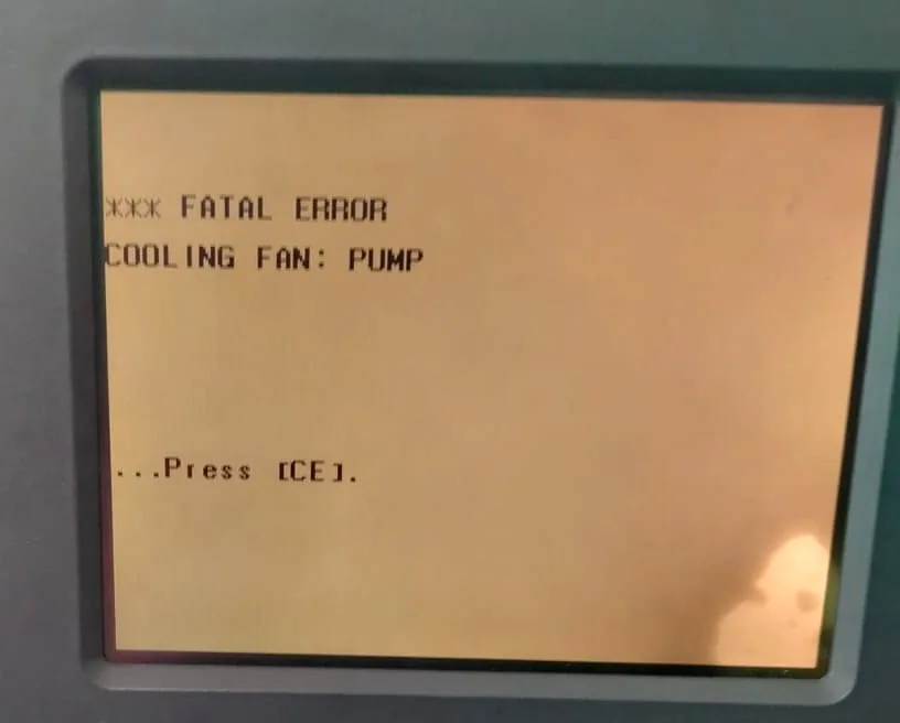
*** FATAL ERROR · COOLING FAN: PUMP · ...Press [CE].
Pressing CE clears the message; it returns within seconds, and the pump
stays locked out the whole time.The cooling fan was working. A single failed transistor was blocking the signal that tells the instrument so. The instrument, believing the fan had stopped, refused to run the pump.
We replaced that one component. The error cleared and the pump started. No board replacement, no new fan.
The complaint
*** FATAL ERROR — COOLING FAN: PUMP on the display. The fan — visible, audible — was turning at
full speed. And because the instrument treats a fan fault as a protection condition,
it would not let the pump run at all. No pump, no flow, no analysis.
A working fan was stopping the entire instrument.
An instrument that refuses to run is expensive. An instrument that refuses to run for a reason that isn’t true is worse — because every obvious fix is the wrong one.
How the instrument actually watches the fan
This is the piece that makes the whole case make sense, and it is the piece most people skip. The CPU never sees the fan. It counts pulses. Two per revolution, generated inside the fan by a Hall sensor, carried on the white wire, and stepped down by one small transistor before reaching the processor. Break that chain anywhere and a perfectly healthy fan reads as a dead one.
The parts involved
| Instrument | Shimadzu LC-2010 / LC-2010CHT |
| Board name | LC2K-CNCT |
| Board part number | 228-37221A |
| Board assembly number | 228-37220-91 |
| Connector | J5 · 3-pin · red / white / black |
| Fan rating | 24 V DC · 0.08 A · 3-wire |
| Component replaced | 2224 9K |
| Its job | Fan detection (FG) · 24 V → CPU level |
| How it failed | Internally shorted |
A note on that marking. 2224 is the part;
9K is a date/lot code, not part of the identity. Codes like this are
manufacturer-specific and easy to misread, so do not order from the marking
alone — confirm the device type by measurement. In this position the component
handles only a few milliamps, so a common small-signal transistor of the correct
polarity will do the job.
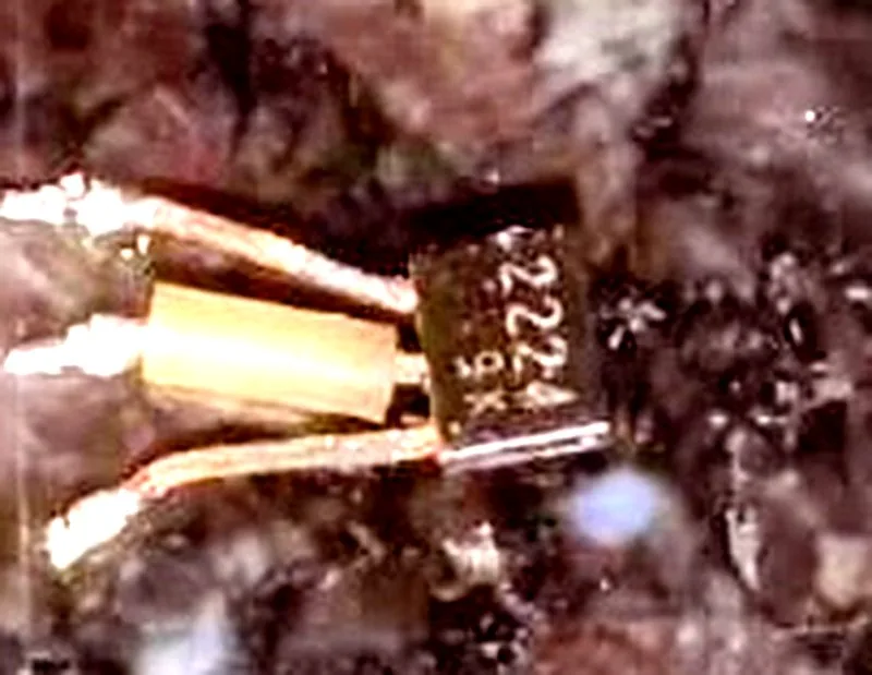
2224 with a lot code beneath.
On the board, in place, that marking was effectively unreadable; this is why we
identified it by continuity instead of by sight.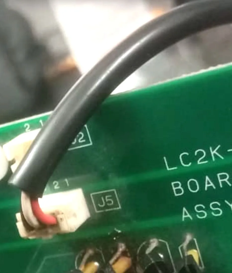
J5 carries the fan’s three
wires: red (+24 V), white (FG / detection), black (ground).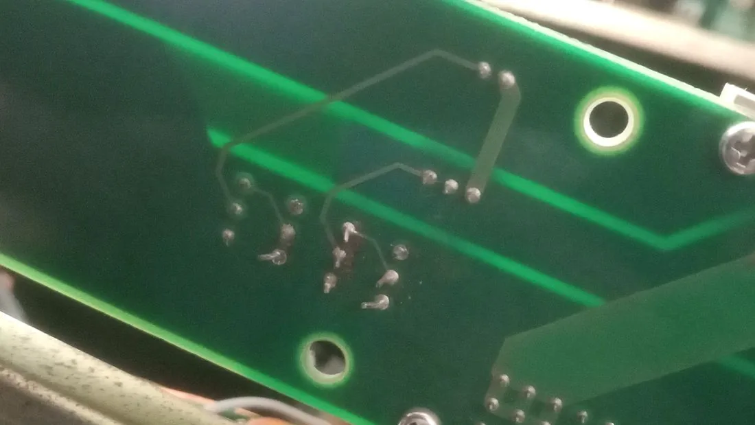
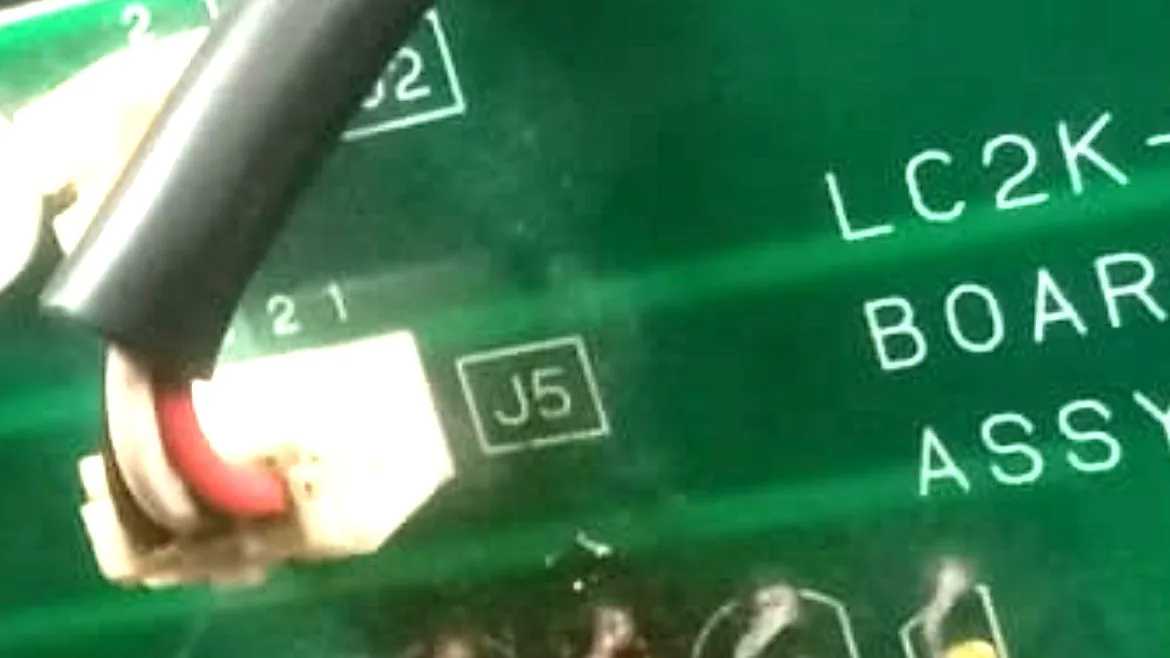
J5 with the fan’s three wires,
and immediately below it the row that carries the detection circuit. The failed
transistor is the first in that row — the one whose centre leg connects back to the
white wire. Note the row is mixed: the black cylinder is a capacitor and the yellow
bodies are not transistors either. Counting “transistors” by eye will mislead you;
continuity will not.What we measured, in order
Count the wires
Three: red, white and black, into J5. The single most common cause of
this fault — a cheap two-wire fan with no tacho output at all — was ruled out in five
seconds.
Correct fan type fitted.
Supply voltage at the connector
Within tolerance. The board is powering the fan properly — which is why it spins.
Supply path healthy.
The detection line — the measurement that mattered
fan unplugged = 2.5 V drifting down to 1.5 V
Both readings are wrong, and the second is the louder one. With the fan removed, nothing external touches that line — the board’s own pull-up should hold it dead steady. It did not. A line that cannot hold itself up can never show a pulse.
Something on the detection line is dragging it down, with the fan out of the circuit entirely.
Find the component — by continuity, not by part number
The board carries no published schematic, and the markings around J5
cannot be decoded reliably. So we did not try. One probe parked on the J5
centre pin, the other touched to every leg of every nearby component.
One beeped — the middle leg of the first transistor.
Two minutes, no documentation, no guessing.
The contradiction that confirmed it
at the transistor’s middle leg = 24 V
One wire cannot be at 0 V and 24 V at the same instant. The transistor had failed internally, holding one side down while the pull-up held the other side up. The earlier continuity beep had been travelling through the shorted transistor, not through the copper — which is exactly why it disappeared once the part came off.
Transistor 2224 9K —
shorted.
The fix
One transistor, replaced. The board went back in, the fan went back on, the instrument powered up — and the error was gone.
Error cleared, and the pump started running again. The fan had never been the problem; the pump had never been the problem. A single failed component between them had been telling the instrument a lie, and the instrument — correctly, by design — refused to pump until the lie was resolved.
What this case is worth remembering for
If you are seeing this error
Before replacing anything, check these three, in order. Each takes minutes and each can end the job: that the fan has three wires; that the supply reaches it (red ↔ black ≈ rated voltage); and that the detection line holds steady with the fan unplugged. If the third one drifts, the fault is on the board — and it is very unlikely to need a whole new board.
A low-RPM “silent” replacement fan can produce this identical error while being brand new and perfectly healthy — if its pulse rate sits below what the firmware expects. Match the original fan’s speed, not just its size and voltage.
A fan error that will not clear is not automatically a fan fault, and rarely a reason to replace a board. Ask for the detection line to be measured before anything is ordered. It takes ten minutes and it is the difference between one component and one board.
We service and calibrate Shimadzu, Waters, Agilent, PerkinElmer and Thermo systems, and repair at component level wherever the fault allows it. Call or WhatsApp 9136216080.